

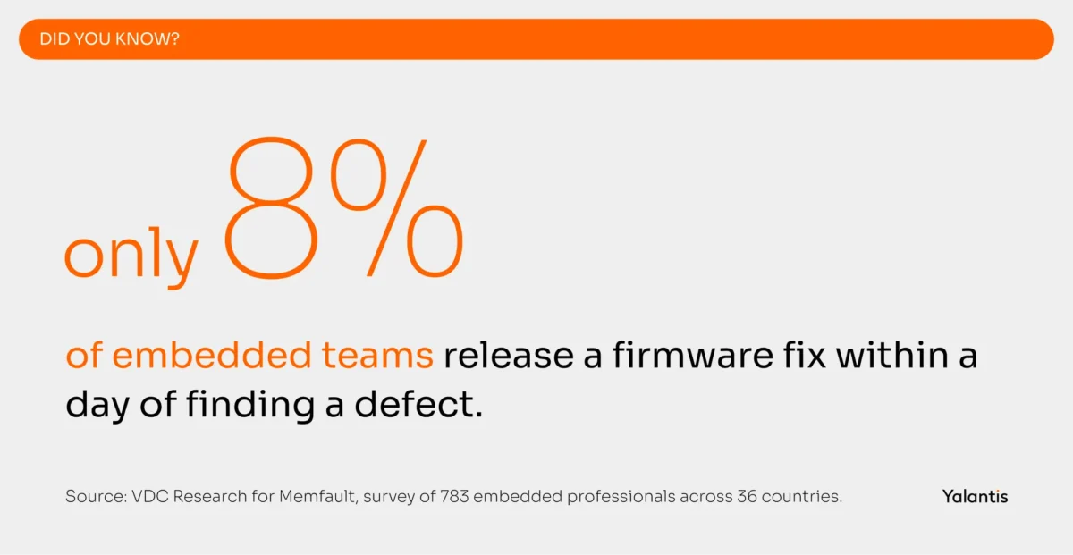
On 11 September 2026, the EU Cyber Resilience Act starts requiring manufacturers to report actively exploited vulnerabilities in connected products within 24 hours. If your team cannot get a verified update onto a fielded device inside that window, this regulation is now your engineering problem. Most teams cannot. Only 8% release a fix within a day of finding a defect.
That number comes from a survey of 783 embedded professionals across 36 countries, run by VDC Research for Memfault. The same study found that 50.3% of teams take more than a week just to find a software defect in the field. For 19.6%, it takes months.
This guide covers firmware development for embedded and IoT devices end to end: what firmware actually is, how the firmware development process runs phase by phase, when bare-metal beats an RTOS, how to design an OTA pipeline that will not brick a fleet, and how firmware compliance plays out across medical, industrial, automotive, and logistics products.
Everything in it comes from devices our engineers have shipped, including the parts we got wrong the first time. Start anywhere you like.
What is firmware development?
Firmware development is the engineering of the persistent, low-level software that controls a device’s hardware directly, running on its microcontroller. It sits below any application layer and it usually ships inside the product, stored in non-volatile memory rather than installed by a user.
That is the short answer. Here is what it means in practice.
Your device has a microcontroller with a fixed amount of flash and RAM and a handful of peripherals. It has no operating system until you put one there. Firmware is everything you write to make that silicon behave like a product: the code that runs first at power-on, the code that talks to each sensor register, the code that decides when to sleep, and the code that implements what the device is actually for.
A typical firmware image has four layers:
- Bootloader. The first code to execute after reset. It initializes the hardware and verifies the signature of the main image before deciding whether to boot it or fall back to a previous version. In a device with over-the-air updates, the bootloader is also where the update gets applied.
- Hardware abstraction layer and board support package.The HAL exists to abstract the hardware, wrapping memory and peripherals behind a stable API. The BSP pins that API to your specific board revision. This layer is where most firmware design and development effort actually goes, and it is the layer most first-time projects underestimate.
- Scheduler or RTOS. Either a bare-metal superloop with interrupt handlers, or a real-time operating system like FreeRTOS or Zephyr managing tasks and timers.
- Application logic. The application firmware layer, holding sensor sampling schedules, control loops, state machines, protocol handling and business rules.
The distinction that trips people up is firmware versus device drivers. Drivers are a part of firmware, specifically the part that translates between your application’s intent and a peripheral’s register map. In embedded firmware development, you frequently write those drivers yourself, because the vendor-supplied ones are either absent or too generic to hit your power and timing targets.
What is the difference between firmware and embedded software?
Firmware is the narrowest of these terms and means code bound to specific hardware. Embedded software sits one layer up, and IoT firmware is firmware that also carries a network stack and an update mechanism, which changes its security and regulatory profile substantially.
Most guides treat these as synonyms. They are not, and the difference determines which standards apply to your product and how much of your engineering budget goes where.
The practical consequence: a bare-metal motor controller that never touches a network has a very different cost structure from a battery-powered sensor that reports to a cloud platform. Adding connectivity to a device does more than add a radio driver. It adds a TLS stack, a certificate lifecycle, an update pipeline, a vulnerability disclosure obligation, and a support commitment that lasts as long as the product does.
That last point is worth sitting with. Under the CRA, a support period expectation attaches to the product, so a connectivity decision made in a two-week feasibility sprint creates a maintenance liability measured in years.
What are the phases of the firmware development process?
The firmware development process runs in eight phases, from requirements through OTA release strategy. In regulated industries the phases are not optional, because each one produces evidence that an auditor will ask to see.
Here is the sequence we run on firmware product development engagements.
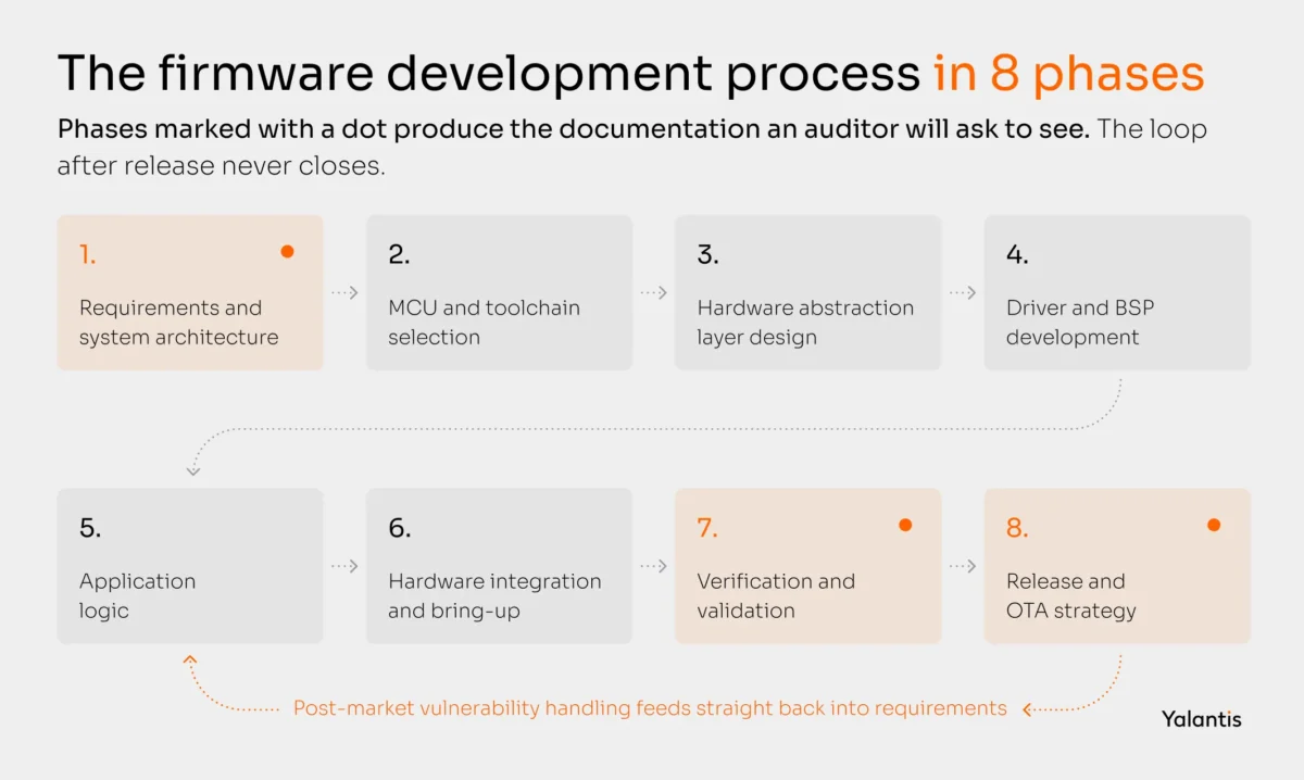
Each phase closes on an artifact rather than a feeling. Phase 1 owes you a system architecture document and a requirements traceability matrix with the performance requirements written down. Phase 2 owes you a silicon decision record with the flash and RAM budget written down. Phase 3 owes you a HAL specification before any driver exists.
Phase 4 owes you a board support package with a bring-up report, and phase 6 owes you power measured on real boards rather than estimated from a datasheet. Phases 7 and 8 owe you the coverage and static analysis reports an auditor will ask for, along with a signed release image and a documented rollback procedure.
Two phases deserve more attention than they usually get.
Phase 2 decides your economics. Choosing a microcontroller sets your unit cost, your available flash for A/B OTA partitions, your toolchain licence costs, and your exposure to a single vendor’s lifecycle announcements. We have seen a project pick a part with 512 KB of flash and build a 300 KB application, then discover that A/B partitioning for safe updates needed 600 KB. The fix was a board respin and a six-week delay. Choose silicon with your OTA scheme already sketched.
Phase 3 is where you buy or lose your future. Defining the HAL boundary before writing drivers feels like overhead in week two. It is what lets you move to a new sensor part in a week instead of a quarter when your original supplier goes end-of-life. In our engagement with Intertape Polymer Group, a global packaging manufacturer headquartered in Sarasota, we designed a scalable and maintainable embedded software architecture for their next generation of automated tape dispensers specifically so that the same firmware base could carry multiple machine variants. The client’s feedback in their public review was about code structure enabling future development, which is the whole point of that phase.
Need a firmware development partner that owns the hardware too?
Tap into our full-cycle team to build your device firmware and the board underneath it, from the sensor to the dashboard.
Should your firmware run bare-metal or on an RTOS?
In embedded firmware development, bare-metal wins when your device has few concurrent activities and time-critical paths. An RTOS wins as soon as you have several independent activities with different timing needs, or a connectivity stack that expects to block.
Bare metal firmware development means your application owns the processor outright, with no kernel arbitrating between tasks. An RTOS inserts that arbitration layer and charges you memory for it.
The decision is usually made by habit rather than analysis, so here is a framework.
When bare-metal firmware development is right. A superloop with interrupt service routines has no scheduler overhead and no context-switch jitter. The control flow reads top to bottom. For a current-sense loop running at 20 kHz, or a device that samples one sensor and blinks one LED, an RTOS adds risk without adding value. Microcontroller firmware development on parts like the STM32C0 or ATtiny series is usually bare-metal by necessity, since the kernel alone would consume the RAM budget.
When an RTOS is right. The moment you have a radio stack and a sensor sampling schedule competing for the same CPU, hand-rolled cooperative scheduling turns into a bug farm. FreeRTOS is the pragmatic default and the most widely deployed. Zephyr has become the stronger choice for connected products, because it ships with a network stack, a device tree, a driver model, and MCUboot integration, which removes weeks of plumbing. ThreadX (now Eclipse ThreadX) remains common where a pre-certified kernel matters for a safety case.
When to consider embedded Linux. If you need a filesystem, a display stack, multiple network interfaces, or the ability to run Python or containers, you have outgrown microcontroller territory. That moves you to a microprocessor with external DRAM, which changes your BOM cost and your power consumption. The trade is real: embedded Linux gives you a vast software ecosystem and costs you deterministic timing and milliamps.
Three architectural concerns cut across all of these.
Task scheduling and priority. Assign priorities from measured timing requirements. A common failure is giving the connectivity task a high priority because connectivity feels important, which then starves the sensor task and corrupts your data at the exact moment the network is congested.
Memory management. Dynamic allocation in long-running firmware causes fragmentation you will not reproduce in testing and will see in the field at month eight. Prefer static allocation and fixed-size pools. If you must allocate at runtime, do it once at init.
Interrupt handling. Keep interrupt service routines short enough to be uninteresting. Set a flag or push to a queue, then exit. Any real work belongs in a task. We have debugged more field failures caused by long ISRs blocking a watchdog than by any other single cause.
Need firmware development for embedded systems that holds up in the field?
Our embedded engineers own the full stack, from bare-metal drivers and BSPs to the application layer above them.
What constraints does IoT firmware add?
IoT firmware development adds two constraints that firmware development for embedded systems without connectivity does not have to solve: a power budget that has to survive years on a battery, and a connectivity stack that has to work when the network does not. Both are architectural decisions, so both have to be made before you write application code.
How do you actually budget power in firmware?
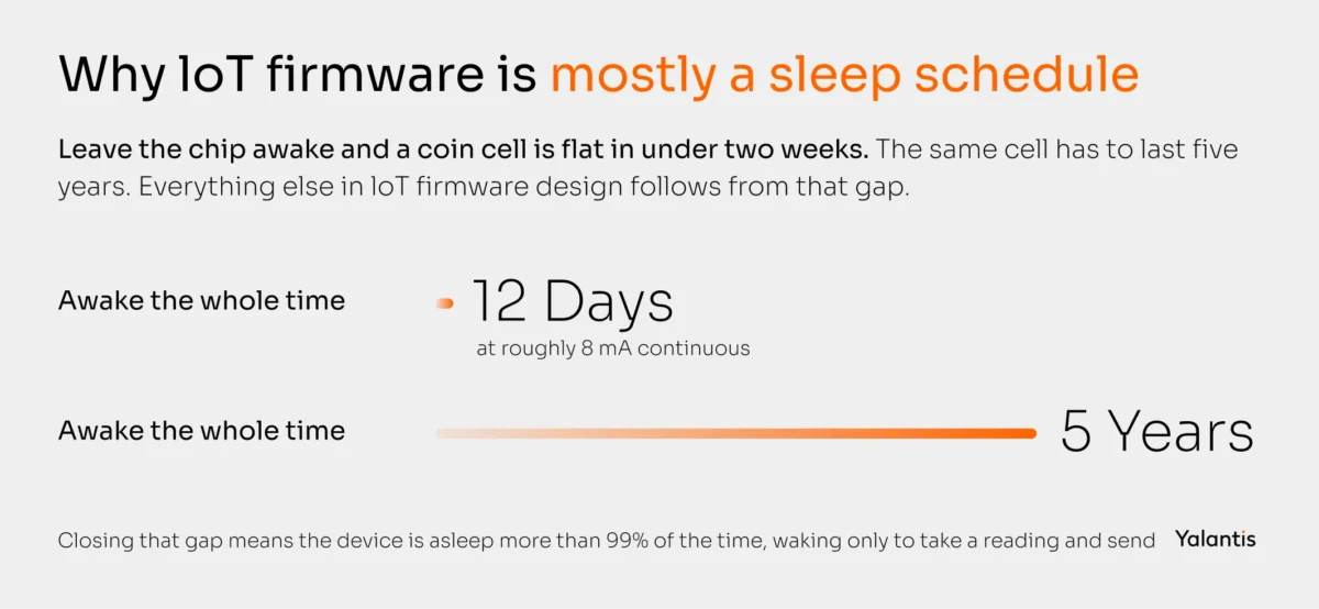
Start from the battery and work backwards. A 2400 mAh cell that must last five years gives you roughly 55 microamps of average current. A typical MCU in active mode draws 5 to 10 milliamps. That is a ratio of about 1 to 150, which tells you your device has to be asleep for more than 99% of its life.
That single calculation reframes the whole firmware design. You are not writing a program that occasionally sleeps. You are writing a sleep schedule that occasionally computes.
Four techniques do most of the work:
- Duty cycling. Power sensors and radios only while they are needed, and measure the actual wake-up cost of each peripheral. Some sensors take longer to stabilize than to read, which makes frequent short reads more expensive than infrequent long ones.
- Deep sleep with the right wake source. Use an RTC alarm or a GPIO interrupt to wake the core, and keep as much SRAM unpowered as your state allows. The difference between a 2 microamp and a 20 microamp sleep mode is the difference between five years and six months.
- Sensor batching. Buffer readings locally and transmit in groups. Radio transmission usually dominates the energy budget, so ten readings in one packet costs far less than ten packets.
- Event-driven transmission. Send on threshold crossings rather than on a fixed schedule. A cold chain sensor that reports only when temperature leaves its band transmits a fraction of what a fixed-interval reporter does.
Choosing a connectivity stack
The radio choice sets your power ceiling and your payload limits. It also decides how much firmware you have to write and certify.
A note on Matter, since it comes up in most consumer and building-product conversations now: the interoperability benefit is real and the firmware cost is higher than teams expect. Commissioning flows and certificate provisioning at manufacture both land on the firmware team, and so does the certification process itself.
Edge processing: how much should the device decide?
Every byte you do not transmit is energy you do not spend, so pushing computation onto the device usually improves battery life and latency at the same time. The limit is your flash and RAM budget, plus your ability to update the logic later.
A reasonable rule: put deterministic filtering and thresholding on the device, and keep anything you expect to tune frequently in the cloud. Anomaly detection thresholds that change monthly do not belong in a firmware image that takes three weeks to roll out safely.
Our work on custom explosion-proof IoT sensors for a Netherlands compressor manufacturer took this route. Sensor firmware handled the local signal conditioning and alerting, while the predictive maintenance models stayed in the platform where they could be retrained.
That split cut the client’s support costs by 52% and contributed to a 20% sales increase. The devices could operate through connectivity gaps, and the models kept improving without a fleet-wide firmware update.
Planning a connected device from the sensor up?
Our IoT firmware development team designs the board and the firmware for IoT devices as one system with the cloud layer above it, so nothing falls between the hardware and software teams.
How does an OTA firmware update actually work?
An IoT firmware update over the air moves through seven steps: build, sign, publish, download, verify, apply, and confirm. Every stage of OTA firmware development has a failure mode you have to design for. The engineering difficulty is concentrated in the last three, because that is where a failure turns a device into a brick.
OTA firmware development is the highest-leverage and highest-risk decision in a connected product. Get it right and you can fix a vulnerability across a fleet in days. Get it wrong and a single bad image takes out your installed base, along with your reputation.
The seven steps
- Build. A reproducible build in CI, tagged with a monotonically increasing version. Reproducibility matters because you will eventually need to prove which source produced a shipped binary.
- Sign. Sign the image with a private key held in an HSM, never on a developer laptop and never in the repository. The device holds only the public key.
- Publish. Upload to an update service with cohort targeting, so you can address a beta group or a specific hardware revision.
- Download. The device pulls the image over TLS, resumably. Assume the connection drops halfway, because on a cellular device it will.
- Verify. Check the signature and a hash before anything is executed. Check the version to prevent a rollback to a known-vulnerable image.
- Apply. Write to the inactive slot and set a boot flag.
- Confirm. Boot the new image and run a self-test. Only mark the image as good once that self-test passes. If the self-test fails or the watchdog fires, the bootloader reverts to the previous slot on the next reset.For a structured starting point, OWASP’s IoT Top 10 and NIST IR 8259 both give a defensible baseline you can map requirements against, which is useful when a customer’s security questionnaire arrives.
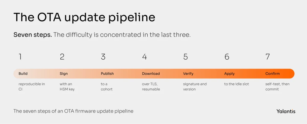
Step 7 is the one teams skip. Without a confirmation step, a firmware image that boots but cannot reach the network is unrecoverable, because the device has no way to receive the fix.
A/B partitioning vs. single-slot swap
A/B partitioning keeps two complete application images in flash. The device runs one and writes the other, then switches. Rollback is instant and safe. The cost is that your application flash requirement doubles, which is exactly the constraint that catches teams who chose silicon before designing OTA.
Single-slot with a staging area stores the incoming image in external flash or an internal scratch region, then has the bootloader copy it over the application. This needs less internal flash. It also creates a window during the copy where a power loss leaves the device with no valid application, so the bootloader must be able to recover and re-request the image.
For anything battery-powered or physically inaccessible, choose A/B. The flash cost is cheaper than a truck roll.
Delta updates
A delta update ships only the difference between two versions, which can cut payload size by 80% or more. On a metered cellular fleet, that is a direct line item. The catch is that delta reconstruction needs the device to hold a byte-exact copy of the current image, so any device that drifted from a known baseline has to fall back to a full image. Plan for both paths.
Staged rollout and observability
Never ship to 100% of a fleet at once. A workable ladder is 1%, then 10%, then 50%, then the rest, with a hold at each step long enough to see a failure signature.
This only works if the devices report back, so the update service needs to see boot success rates and crash reports per cohort. Being able to manage a device fleet remotely is the difference between catching a bad update at 1% and hearing about it from customer support at 100%.
OTA tooling you do not have to build
You rarely need to build this from scratch. Mature options include AWS IoT Device Management jobs, Azure Device Update for IoT Hub, ESP-IDF’s native OTA for Espressif parts, MCUboot, one of the few bootloaders that works across Zephyr and other RTOSes, Mender for embedded Linux, Nordic’s nRF Cloud FOTA, and Memfault for combined observability and rollout control.
Where does firmware security have to start?
IoT firmware security rests on a hardware root of trust and a verified boot chain, so that a device will only execute code signed by you. Everything else, from encrypted images to locked debug ports, hardens that foundation.
Firmware is a favoured target because it is where the keys live and it is rarely inspected. A compromise also persists through a reboot. IoT firmware vulnerabilities also tend to be systemic: one flaw in one image is one flaw across every unit shipped.
The scale is documented. The 2025 CISA and NSA guidance on memory-safe languages reports that 75% of CVEs used in active attacks were memory safety flaws, citing Google Project Zero. Of the 58 in-the-wild zero-days found in 2021, 67% were memory corruption.
The CISA and NSA joint guidance on memory safe languages published in 2025 cites BadAlloc, a set of memory allocation flaws the agencies put at more than 195 million vehicles and critical infrastructure devices. Memory safety CVEs in industrial control systems grew from under 1,000 in 2014 to nearly 3,000 in 2023.
The threat model
Seven surfaces carry most of the risk. The image at rest can be extracted and reverse engineered, which is what image encryption and flash readout protection are for. The boot process can be handed a malicious replacement. The update channel can be intercepted or walked backwards to an older signed release, so TLS with certificate pinning belongs alongside your signature checks.
Keys can be lifted straight out of application flash, which is why they belong in a secure element or a TPM. Some microcontrollers provide their own secure enclave for the same job. Runtime memory can be overflowed into code execution. Memory protection unit regions and stack canaries make that harder, and writing the parsing code in a memory-safe language removes the class outright.
The last two surfaces are the ones teams forget. Third-party libraries carry known CVEs whether or not you track them. And physical interfaces stay open more often than anyone admits, so production fuses get blown and the UART console gets disabled in release builds.
The non-negotiables
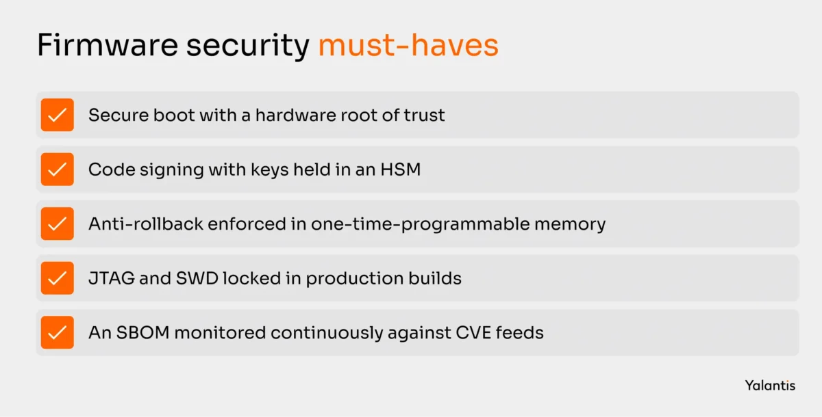
Secure boot with a hardware root of trust. The first-stage bootloader must live in immutable memory or be protected by a hardware fuse, and it must verify the next stage before executing it. Without an immutable anchor, a signature check is theatre, because an attacker who can rewrite the verifier can rewrite the verdict.
Code signing with real key management. Private keys in an HSM. Separate keys for development and production. A documented key rotation procedure you have actually rehearsed.
Anti-rollback. A monotonic version counter in one-time-programmable memory, checked before an image is accepted. Otherwise your carefully patched fleet can be walked back to a vulnerable release.
Debug interface lockdown. JTAG and SWD open in production is one of the most common findings in firmware audits, and one of the easiest to close.
An SBOM and a remediation clock. Generate a software bill of materials in CI for every release, and monitor it against CVE feeds continuously. This is now a legal requirement in the EU, and it changes the shape of the work: IoT device firmware remediation stops being a reactive scramble and becomes a scheduled process with a service-level target attached. Most of the work of preventing IoT firmware vulnerabilities happens here, in the boot chain and the update path, long before a CVE is ever filed against your product.
For a structured starting point, OWASP’s IoT Top 10 and NIST IR 8259 both give a defensible baseline you can map requirements against, which is useful when a customer’s security questionnaire arrives.
Worried about what a firmware audit would find?
We build secure boot and signed update pipelines into IoT device firmware in the first sprint, with keys stored in hardware from day one.
What certifications apply to firmware in regulated industries?
Firmware compliance is driven by two separate families of standards: functional safety and quality standards tied to your industry, and cybersecurity regulations tied to the fact that your product connects to a network. Most connected products in regulated markets now have to satisfy both.
This is the section where firmware projects most often lose a quarter. Developing firmware for a regulated market is a documentation and traceability problem as much as an engineering one, and documentation you did not produce during development cannot be reconstructed afterwards in a way an auditor will accept.
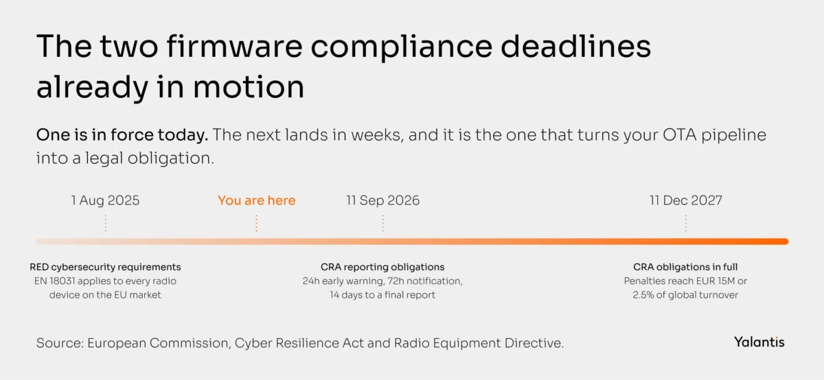
The two deadlines that matter right now
EU RED cybersecurity requirements are already in force. Since 1 August 2025, radio equipment placed on the EU market must meet Articles 3(3)(d), (e) and (f) of the Radio Equipment Directive, with EN 18031-1, -2 and -3 as the harmonised standards. Those were cited in the Official Journal with restrictions, notably around Article 3(3)(d) and user-defined passwords, so they give only a partial presumption of conformity. If your device has a radio, this is a CE-marking gate you pass today.
The Cyber Resilience Act arrives in two stages. The CRA entered into force on 10 December 2024. Reporting obligations apply from 11 September 2026: an early warning within 24 hours of becoming aware of an actively exploited vulnerability, then a full notification within 72 hours. A final report follows within 14 days of a corrective measure becoming available. All remaining obligations apply from 11 December 2027. Penalties are tiered. Breaching the Annex I essential requirements or the Article 13 and 14 obligations reaches 15 million euros or 2.5% of global annual turnover. Other obligations carry 10 million euros or 2%, and supplying incorrect information to authorities carries 5 million euros or 1%. The Commission published its final implementation guidance on 27 July 2026, roughly 80 pages of worked examples, which is worth reading before your next architecture review.
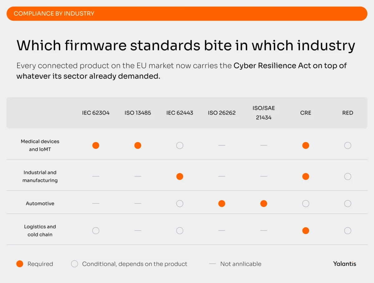
Compliance by industry
Yalantis holds ISO 9001, ISO 13485, ISO 27001, and ISO/IEC 27701 certifications, and works to IEC 62304, IEC 62366-1, IEC 82304-1, IEC 62443, and IEC 81001-5-1. In practice that means the design controls an auditor wants are produced as the firmware is written.
On a medical programme that means fitting IEC 62304 and ISO 13485 into an embedded sprint cadence, so traceability accrues with every merge instead of being assembled in a panic before submission.
Facing a CRA or IEC 62443 deadline?
We build the compliance evidence into the firmware development process, so certification stops being a phase you fear at the end.
What tools does a firmware development team need?
The firmware toolchain has four parts you choose deliberately: an integrated development environment and compiler, a hardware debugger, a build system, and a CI pipeline that can run tests on real silicon. The last one is where most teams are weakest.
Where firmware low-code development helps, and where it hurts
Vendor code generators have become genuinely good. STM32CubeMX, MCUXpresso Config Tools, and Zephyr’s devicetree let you configure clocks and peripherals graphically and emit initialization code. Used well, firmware low code development removes a week of tedious register work per board revision and eliminates a category of copy-paste errors.
It hurts in two places. Generated code often regenerates over your edits, so anything you customize needs to live outside the generated regions or in your own wrapper.
Generated initialization also tends toward safe defaults rather than power-optimal ones, which is why a device built entirely from generator output frequently draws two to three times its target sleep current. Use the generator for the first pass, then measure and hand-tune the power path.
How do you test embedded firmware?
Firmware testing works in four layers to validate a build against its requirements: unit tests on host, integration tests on host with mocked hardware, hardware-in-the-loop tests on real boards in CI, and fuzz testing on anything that parses external input. Static analysis runs across all of them.
The reason to build this properly sits in the Memfault data cited at the top of this guide. Testing is where embedded firmware development either earns its reliability or borrows against it. Teams that take a week to find a field defect are not slow debuggers. They have no observability and no regression suite, so every issue starts from scratch.
- Unit tests on host. Unity with CMock, wrapped by Ceedling, is the established C combination. GoogleTest works well for C++. Zephyr projects get ztest. The prerequisite is a clean HAL boundary, which is why phase 3 of the lifecycle matters so much: code that touches registers directly cannot be unit tested off-target.
- Integration tests with mocked peripherals. Simulate an SPI or I2C sensor returning out-of-range values, or a flash memory write failing mid-operation. These are the paths that break in the field and never get exercised on a bench.
- Hardware-in-the-loop. A rack of target boards attached to a CI runner, with programmable power supplies and signal injection. HIL is the only way to catch timing regressions, and it is the piece teams defer indefinitely because it needs capital and rack space. Build a small one early. Two boards on a Raspberry Pi with a relay board catches more than nothing, and it grows.
- Fuzzing. Point a fuzzer at every parser that touches untrusted input: your OTA image parser, your BLE GATT handlers, your protocol decoders. libFuzzer against host-compiled parsing code finds real bugs quickly.
- Static analysis. Analysis tools such as Coverity, Polyspace, PC-lint Plus, or clang-tidy with a MISRA C profile. In regulated work, static analysis reports are part of your evidence package, so run them in CI from the start rather than producing them retroactively.
Firmware is only one layer of the problem. Testing a connected product end to end means proving that the seams between a device and its backend hold under the same failure conditions you injected on the bench.
Why is Rust gaining ground in embedded firmware?
Rust eliminates memory safety bugs at compile time, which removes the vulnerability class behind roughly three quarters of exploited CVEs. For safety-critical firmware it is now a defensible choice rather than an experimental one, because the toolchain has been formally qualified.
The evidence is straightforward. Google’s Android platform moved new components to memory-safe languages and watched memory-related vulnerabilities fall from 76% of its CVEs in 2019 to 24% in 2024, without rewriting the existing codebase.
CISA’s Product Security Bad Practices guidance also asked manufacturers to publish a memory safety roadmap by 1 January 2026. That turns Rust from a technical preference into a procurement question your customers will ask.
The qualification story closed the last real objection. Ferrocene, the qualified Rust toolchain from Ferrous Systems, is TÜV SÜD-qualified for ISO 26262 up to ASIL D, IEC 61508 up to SIL 3, and IEC 62304 Class C. As of the 26.02 release in early 2026, a certified subset of the Rust core library carries ISO 26262 ASIL B and IEC 61508 SIL 2 certification, which was the piece embedded teams were waiting for.
Selective migration is the practical path. Which of the three strategies for moving an embedded C or C++ codebase to Rust fits you depends on how much of the existing firmware code is worth preserving. Start with the components where a single memory error is catastrophic, meaning boot verification logic and anything that parses network input, and leave working, well-tested drivers in C.
The crate ecosystem for Rust on constrained IoT hardware has matured enough that a new peripheral driver written in Rust now costs about what one in C would.
Considering Rust for your next firmware generation?
We help embedded teams migrate the security-critical parts of a C codebase to Rust without stopping the roadmap.
How does firmware development differ by industry?
The same IoT firmware development discipline produces very different projects depending on the vertical, because the binding constraint changes. For instance, in medical devices, it is documentation. In industrial systems, it is protocol complexity and equipment lifespan. In automotive, it is functional safety. In logistics, it is power consumption.
Medical devices and IoMT
IEC 62304 assigns your software a safety class of A, B, or C based on the harm a failure could cause, and that class determines how much verification and documentation you owe. Class C work needs unit-level verification with traceability from every requirement through design to a specific test result.
The practical implication for firmware architecture is segregation. Isolating safety-critical functions into a separately verified module lets you classify the rest of the firmware lower, which can cut your documentation burden substantially. Deciding this after the architecture is fixed is far more expensive than deciding it in phase 1. Add ISO 14971 risk management and ISO 13485 design controls on top, plus MDR or FDA submission documentation.
Our ISO 13485 certified team takes a medical device from firmware architecture through the design controls your submission will be judged on.
Industrial and manufacturing
Manufacturing firmware development happens in an environment of installed equipment that will outlive several generations of your product. You will meet Modbus RTU alongside MQTT alongside OPC UA, sometimes in the same cabinet, and you will be asked to retrofit connectivity onto a controller whose documentation was lost.
IEC 62443 governs the security side and expects a documented secure development lifecycle plus a patch management process, which is precisely where an OTA capability stops being a feature and becomes a compliance requirement. The other hard constraint is OT and IT segmentation: your firmware often sits at that boundary, and the network design determines what your update path can even look like.
We write the firmware and the protocol bridges that put legacy controllers on a modern network without breaking OT segmentation.
Automotive
A modern electric vehicle runs on the order of 100 million lines of code across hundreds of electronic control units, with a service life above 20 years. ISO 26262 sets the functional safety framework with ASIL classification, and it constrains your toolchain, since a qualified compiler becomes a requirement rather than a preference.
The regulatory layer is what makes automotive OTA distinctive. UN R155 requires a certified cybersecurity management system and UN R156 requires a software update management system, both as prerequisites for vehicle type approval across the EU and dozens of other markets.
R156 means your update mechanism has to be auditable: every campaign approved, every vehicle’s applicability recorded, every outcome logged. ISO 24089 is the usual implementation standard for that process.
We design ECU firmware and staged update campaigns with the approval trail that vehicle type approval asks for.
Logistics and cold chain
Cold chain and asset tracking firmware is a power engineering problem first. Devices ship inside a pallet, run for a year on a coin cell or a small primary battery, and cannot be serviced. BLE handles the local read and LoRaWAN or LTE-M handles the long haul. Event-driven transmission is what keeps the battery alive.
Where the payload is GxP-regulated, the firmware also has to produce an audit trail: timestamped readings that cannot be silently modified, with a monotonic clock that survives a reset. That requirement usually means a secure element and a battery-backed RTC, which are phase 2 decisions.
We engineer low-power sensor firmware with the tamper-evident audit trail that GxP cold chain shipments require.
Should you build a firmware team or hire a partner?
Build in-house when firmware is your core product differentiator and you can keep the team busy after launch. Bring in a partner when you need capability you do not have, on a timeline that does not allow for hiring.
The people who build firmware for constrained targets are among the harder embedded hires, and the skills you need are not interchangeable. A strong application-layer firmware developer is not necessarily the person who can bring up a new board or write a driver from a datasheet.
Three models are worth comparing honestly.
- Full in-house gives you maximum control and the slowest start. Expect six to nine months to hire a capable embedded firmware development team in most markets, longer if you need regulatory experience.
- Team augmentation adds specific capability to an existing team. This works when you have technical leadership in place and a clear architecture. It fails when you use it to substitute for the architecture decision itself.
- Full outsourcing makes sense for a first connected product, or when the whole hardware and firmware stack is new to you. The thing to check is whether the partner can actually cover hardware. A firmware team without board access will hand you integration risk at the worst possible moment.
What are the most common firmware development pitfalls?
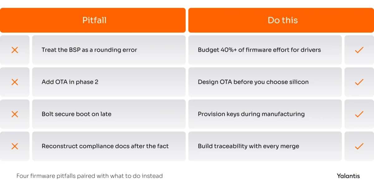
Six failures account for most firmware rework. All of them cost money, and the third one, retrofitting OTA, is the one that forces a board respin.
- Underestimating BSP and HAL work. Teams budget for the interesting application logic and treat drivers as a rounding error. On a new board, the BSP and driver layer routinely consumes 40% or more of the embedded firmware development effort. Budget it explicitly.
- Deferring hardware-in-the-loop testing. HIL always looks like something to build after launch. Then the first field regression arrives and you have no way to reproduce it. Start with two boards on a CI runner in month two.
- Treating OTA as a phase-two feature. This is the expensive one. Retrofitting over-the-air updates changes your memory map and your bootloader. Often it changes the board too. Decide the OTA scheme before you choose silicon.
- Leaving security to the last sprint. Secure boot with a hardware root of trust cannot be bolted on, because it depends on silicon features and manufacturing provisioning steps. A device that shipped without a key provisioning process in production has no path to secure boot without a hardware change.
- Underdocumenting for compliance. Traceability that was not created during development cannot be credibly reconstructed. Auditors recognise retrospective documentation, and the remediation cost usually exceeds what doing it properly would have cost.
- Accumulating C technical debt with no migration plan. Nobody expects you to rewrite a working codebase in Rust. Customers and regulators increasingly do expect a memory safety roadmap. Not having one is now a procurement risk as much as a technical one.
Why choose Yalantis for firmware development?
Because the choices that decide a firmware programme get made in the first two weeks, and we make them with the hardware engineers in the same room.
Getting the microcontroller and the update path right and a patch is a two-day job. Get them wrong and it is a board respin. We recommend building the unglamorous parts first, because a signed OTA path and a test rack with real boards keep you fast for years afterwards.
Our R&D lab in Warsaw is built for exactly that. PCB design and prototyping sit alongside firmware, so nothing falls between the hardware and software teams. We are a compliance-first partner with 17+ years of work and 400+ specialists, and the design records an auditor asks to get produced as the code is written.
If you are weighing one of those decisions right now, we are glad to be useful.
FAQ
What is the difference between firmware development and software development?
Firmware development targets a specific piece of hardware and produces code that runs without a general-purpose operating system, inside fixed flash and RAM limits. Application software development targets an OS that abstracts hardware away. The practical differences: firmware has no meaningful debugger in the field and cannot be updated casually. It also has to account for physical failure modes like power loss during a flash write.
What is the firmware development process?
Eight phases: requirements and system architecture, MCU and toolchain selection, HAL design, driver and BSP development, application logic, hardware integration and bring-up, verification and validation, then release and OTA strategy. In regulated industries each phase produces documented evidence, and the process loops after release for post-market vulnerability handling.
What programming languages are used in firmware development?
C dominates firmware for microcontrollers, with C++ common on larger parts and Rust growing quickly in safety-critical and security-sensitive work. Assembly appears in startup code and tight interrupt paths. Python is used heavily for build tooling and test harnesses rather than for on-device code.
How do you secure IoT firmware?
Start with a secure boot anchored in a hardware root of trust, so the device only runs code you signed. Add signed updates with anti-rollback enforcement, keys held in a secure element rather than application flash, encrypted images, and debug interfaces disabled in production. Then generate an SBOM in CI and monitor it against CVE feeds so you can meet a remediation deadline.
How do over-the-air (OTA) firmware updates work?
An IoT firmware update starts as a signed image published to an update service, the device downloads it over TLS, verifies the signature and version, writes it to an inactive flash slot, and reboots into it. A self-test confirms the new image is healthy. If the check fails, the bootloader reverts to the previous slot. Staged rollout to a small cohort first, with telemetry reporting back, is what keeps a bad release from reaching the whole fleet.
Which firmware standards apply to my industry?
Medical devices need IEC 62304 and ISO 13485 with ISO 14971 risk management. Industrial systems need IEC 62443. Automotive ECUs need ISO 26262, ISO/SAE 21434, and UN R155 and R156 for type approval. Any connected product on the EU market falls under the Cyber Resilience Act, and any radio device falls under the RED delegated regulation, which has been in force since August 2025.
How is IoT firmware different from embedded firmware?
IoT firmware is embedded firmware plus a network stack and a credential lifecycle, with a remote update mechanism on top. Those additions bring cybersecurity regulation and a multi-year support obligation, along with a substantially larger attack surface. A non-connected embedded device is engineered once. An IoT device is engineered and then maintained for its whole service life.
When should you outsource firmware development?
Outsource embedded firmware development when you need a capability you cannot hire in time, when you are building your first connected product and the hardware and firmware stack is new to you, or when a compliance deadline requires regulatory experience your team does not have. Keep it in-house when firmware is your core differentiator and you have enough sustained work to retain a team after launch.
About the author